7. Prototype
7.1 Overview
The prototype is a basic implementation of the Test Suite. It presents possible solutions for the requirements which are defined in this diploma thesis. The implemented functionality in the prototype is limited to the scope of this thesis. It does not represent a full featured Test Suite. The development of the prototype has been concentrated on a few features, which are able to show the framework integration, the use of different UI technologies as well as the shortcomings of the CAB framework. The result is an infrastructure block and a collection of modules that show different aspects of the requirements.
7.2 Architecture
The prototype is primarily a .NET 2.0 application that runs on top of the Composite UI Application Block. One module uses the new UI technology called Windows Presentation Foundation already which is part of the .NET Framework 3.0 (Figure 9). Important to note is that the .NET Framework 3.0 is built on top of the .NET Framework 2.0 and introduces four new framework libraries only. WPF is one of them. The .NET Framework 3.0 does not change the common language runtime (CLR) or the base class library (BCL) of the .NET Framework 2.0. That is the reason why it is possible to mix .NET 2.0 and .NET 3.0 assemblies in one application.
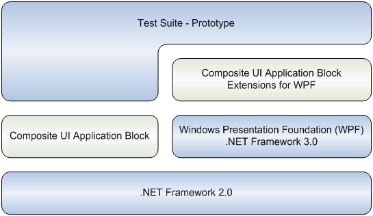
Figure 9: Prototype architecture.
Besides the usage of CAB and the extensions of SCSF as an application framework, some further libraries are used in the Test Suite:
- The Exception Handling Application Block allows to define a consistent handling for all exceptions that occur in the application. It is part of the Enterprise Library 3.1.
- The Logging Application Block extends the logging functionality of the .NET Framework. It is part of the Enterprise Library 3.1 too.
- The DockPanel Suite is a docking library for Windows Forms controls. It mimics the look and feel of the Visual Studio 2005 IDE. The library is licensed under the open source MIT license.
- The CAB Extension is a library which was developed during the implementation of the prototype. It adds some reusable features to the Composite UI Application Block.
7.3 Modules
This chapter gives a short overview of the implemented modules that can
be used by the Test Suite. Figure 10 uses an UML component diagram to show
the modules with their dependencies to each other. Every component with the
stereotype <<cab module>> represents a .NET assembly which implements a CAB
module. The interfaces shown in Figure 10 are implemented as separate .NET
assemblies. They provide all the necessary information for a CAB module to
use and extend the module which implements the interface assembly. It is
also possible to divide the implementation of an interface assembly into
more CAB modules like it is done with the Infrastructure.Interface assembly.
An interface assembly consists of Interfaces to decouple the service
implementation and string identifiers to access the UI integration
functionality of the Composite UI Application Block. An advantage of this
approach is that the modules can be replaced on both sides of the interface
assembly. This is done for isolating a single module during unit testing.
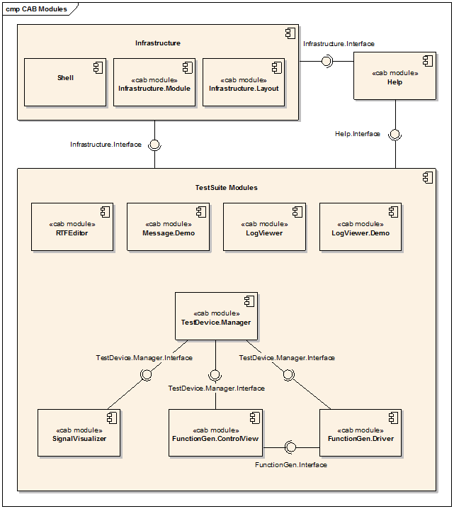
Figure 10: An UML component diagram that shows the
modules of the Test Suite.
Infrastructure
The Infrastructure block in Figure 10 contains the core of the Test Suite
application. All CAB modules require the functionality which is provided by
the infrastructure. Thus, the implementation of the infrastructure must be
loaded first by the application. The implementation is divided into three
modules:
ShellInfrastructure.LayoutInfrastructure.Module
This allows the replacement of one module without affecting the others.
For example, the Infrastructure.Layout module can be replaced by another one
to define a new UI layout for the application.
Many of the infrastructure functions are implemented as CAB services.
These services can be retrieved by the Dependency Injection implementation
of the Composite UI Application Block. If Dependency Injection cannot be
used, the services can be fetched from the WorkItem, which implements the
Service Locator pattern.
The Shell is the .NET assembly that contains the start-up code of the
application. It is responsible to initialize the application and to
configure the CAB framework. The Shell contains a message service for
showing all kinds of messages to the user. The reason for implementing the
message service in this assembly is that an exception can already occur
during the application start-up. The Shell processes all unhandled
exceptions that are thrown in any module of the application. An unhandled
exception is shown to the user with the message service and is logged by the
Logging Application Block.
The Infrastructure.Layout module defines the appearance of the
application. It uses the DockPanel Suite library to define a user interface
layout that is very similar to the one of the Visual Studio 2005 IDE. A
Workspace14 is necessary for using the features of CAB
to host views inside the DockPanel control. The CAB Extension library
contains an exemplary DockPanelWorkspace which is used by the Test Suite
application. This DockPanelWorkspace is able to host Windows Forms and WPF
user controls. Additionally, the layout module registers UI elements as
UIExtensionSites15 so that other modules can extend
them (e.g. the menu bar). Furthermore, this module registers common commands
like copy and paste. Figure 11 shows a screenshot of the Test Suite. It
contains markers to show which CAB parts are behind the UI elements.
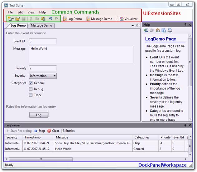
Figure 11: Shows the UI elements of the Test Suite.
The Infrastructure.Module contains further services:
- The
IUIElementCreationServiceis used for creating UI elements which can be added toUIExtensionSites. This service helps to decouple the modules from the UI technology used by theShell. - The
IDocumentManagerhandles the document lifecycle tasks and keeps track of all registered document types. This service mediates between the user interface and the document. A module developer, who has to implement a new document type, does not have to care about things like configuring theOpenFileDialogcomponent or enabling and disabling the save buttons. - The
IEditManagermaps the basic edit functions (e.g. copy, paste …) of an object to the edit menu of the application. Like theIDocumentManager, this service also mediates between the user interface and an object. This object needs to implement theIEditHandlerinterface. Many of the Windows Forms controls and the WPF controls provide some of the methods which are required by theIEditHandlerinterface. An adapter is necessary for using one of the UI controls as an edit handler. This module already contains a few adapters for common UI controls like the WPFTextBox. To simplify the registration of an object for theIEditManager, this module contains an adapter factory catalog. - The
AdapterFactoryCatalog<IEditHandler>service is used to register newIEditHandleradapters and retrieve adapters for a specific object. In Listing 12 the two WPFTextBoxcontrolsscaleXandscaleYare registered at theIEditManagerservice. An important fact is that these objects do not implement theIEditHandlerinterface. Thus, theRegistermethod asks theAdapterFactoryCatalog<IEditHandler>for an appropriate adapter. By using this adapter factory catalog, the module developer does not have to care about theIEditHandlerinterface as long as an adapter is already registered for the needed object type.
1 [ServiceDependency]
2 public IEditManager EditManager
3 {
4 set
5 {
6 editManager =
value;
7
editManager.Register(scaleX);
8
editManager.Register(scaleY);
9 }
10 }
Listing 12: Registering of two WPF TextBox controls to the
IEditManager.
Help
Figure 10 shows a dependency between the Test Suite modules and the
Help module. This module is optional because it is not part of the
Infrastructure. A module developer has to keep in mind that the
service, which is provided by the help module, might not be available. Thus,
a module has to check if the help service is available before it can be
used. The Help module shows the help topics inside a
WebBrowser control. The prototype uses HTML files for the
help pages.
Demonstration Modules
Three CAB modules in Figure 10 just demonstrate some of the functionality which is provided by the infrastructure. These modules are guidelines for using the infrastructure of the Test Suite. The modules are:
LogViewerLogViewer.DemoMessage.Demo
The LogViewer module allows the user to see the log entries
in an application window. This module uses the logging mechanism of the
Logging Application Block. The LogViewer provides a
CustomTraceListener which can be configured in the application
configuration file. The configuration can contain different filter criteria
to limit the log entries, which are shown in the LogViewer
module.
The LogViewer.Demo is a sample module for showing how to use
the logging mechanism of the Logging Application Block. This module contains
a view to define the various log entry properties. A click on the log button
writes the log entry to the logger. The written log entries can be seen in
the LogViewer module, in a text file or somewhere else. The
output depends on the configuration of the logging mechanism.
The Message.Demo module is a demonstration of the message
service provided by the Infrastructure. It allows the user to
show messages in a modal dialog, to update the application status bar and to
throw a predefined exception. The function to throw an exception is used to
see the reaction of the application on unhandled exceptions. By default, the
application shows unhandled exceptions through the message service and logs
the occurrence of the exception via the Logging Application Block.
Editor
The RTFEditor module is an example to show how document
oriented applications can be created with the Composite UI Application
Block. In a real Test Suite the documents would be test reports with the
feature to add some notes by the user. For simplicity, the document in the
prototype is a RTF file.
The module shows that the lifecycle of a WorkItem can be
used to represent the lifecycle of a document. The WorkItemController,
which is aggregated by the WorkItem, implements all the
necessary functionality of a document object. The controller also has the
responsibility to show the document inside the Test Suite user interface.
The RTFEditor module uses the IDocumentManager to
control the document lifecycle. This service decouples the module from the
application because the module is not aware of how the application shows the
create, open, save and close functionality of the documents to the user.
This module uses the IEditManager too. This service mediates
between the application user interface and the RichTextBox
control which is used to show the document. Thus, the module does not need
to care about things like disabling the cut and copy button if no text is
selected.
Test Device Management
The CAB modules, which are shown at the bottom of Figure 10, are
responsible for the management of various test devices. The main module is
the TestDevice.Manager. This module is responsible for the
lifecycle of the test devices. It shows the connected devices in a list as
it can be seen in Figure 12. The user is able to configure and to disconnect
one or more connected test devices. The prototype does not contain modules
for handling real test devices. Thus, virtual test devices were invented.
The TestDevice.Manager module is in charge for creating virtual
test devices. The function generators shown in Figure 12 are virtual devices
too.
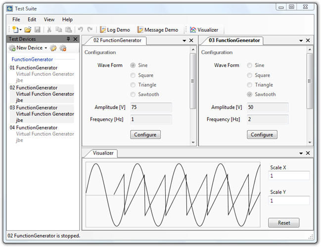
Figure 12: A screenshot of the Test Suite with the TestDevice.Manager.
All of the following modules are depending on the functionality which is
provided by the TestDevice.Manager module (Figure 10). This
functionality does not only consist of services. It also includes an
UIExtensionSite, Commands and a loosely coupled event.
This shows that every CAB module is able to provide its own user interface
extensions for other modules.
The FunctionGen.Driver module represents a driver for
virtual function generators. A driver module is responsible to inform the
TestDevice.Manager about connected and disconnected test
devices. In the case of virtual test devices, the manager triggers the
creation of new devices. It is transparent for the TestDevice.Manager
if a test device is a real one connected to the computer or a virtual one
created by the driver module. The driver contains information about the
supported test devices. This information is read by the manager. The virtual
function generator of the FunctionGen.Driver module is able to
create sine, square, triangle and sawtooth wave forms. Furthermore, the
amplitude and the frequency can be configured. This module does not contain
any UI elements to configure the virtual function generators. This is in the
responsibility of the FunctionGen.ControlView.
The FunctionGen.ControlView module controls device drivers
of the category function generator. It contains UI elements for the user to
manage the device configuration and the device status. Figure 12 shows the
UI elements of this module. The separation of the driver and controller view
responsibility into different modules has the advantage that the controller
view can be reused. The FunctionGen.ControlView is not bound to
the FunctionGen.Driver module. The controller view can also be
used for other function generator drivers. A new function generator driver
just implements the interfaces of the FunctionGen.Interface
assembly. Additionally, the driver has to register at the
TestDevice.Manager module with the same profile name as the
FunctionGen.ControlView does.
Figure 13 shows the process of how to create a new virtual function
generator. The stereotypes in the sequence diagram contain the information
from which module an object comes from. In this case the
TestDeviceManager has the role of the actor because the manager is in
charge for triggering the creation of virtual test devices. The interesting
aspect of this process is that all needed services are registered at the
same WorkItem. This way the FGenControlView object
can access the driver services to control the test device.
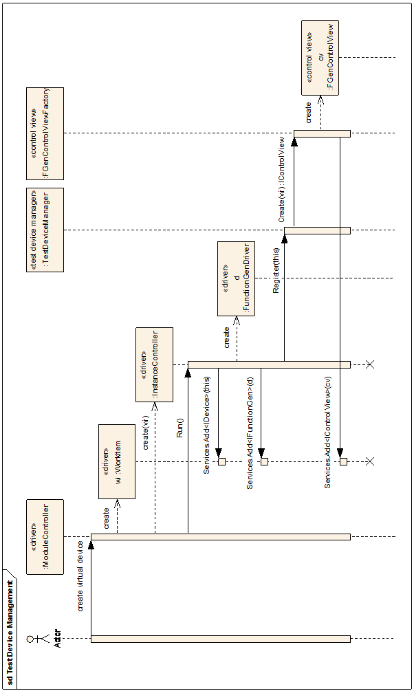
Figure 13: A simplified UML Sequence diagram of creating a new virtual
device.
The SignalVisualizer module draws a graph of one or more
signals. Figure 12 shows the visualizer at the bottom of the screenshot. In
the screenshot two graphs are visible. These graphs are created by two
different function generators which are running simultaneously. The signals
are typically raised by the device drivers. The loosely coupled event
mechanism of CAB is used to carry the signal from the source to the
visualizer. The source creates a SampleEventArgs object which
contains the amplitude and the timestamp of the signal sample. This object
is sent through the loosely coupled event mechanism to all interested
receivers. The visualizer is one of them. The reason for this design
strategy is the decoupling of the visualizer module by using the CAB event
broker. This module does not have any dependency to the
FunctionGen.Driver module which acts as signal source. The
SignalVisualizer is the only module of this prototype application
which uses WPF controls. However, it can be completely integrated into the
Test Suite application, although the application uses the Windows Forms
technology.
14 See also Shell Services (p. 21).
15 See also Shell Services (p. 21).